| ||
| ||
| ||
| ||
| ||
| ||
|
SS7/SIGTRAN/VoIP Security Network
Description: OpenSS7 Application Design Documentation.
The SS7/SIGTRAN/VoIP Security Network product provides a laboratory platform for SS7/SIGTRAN/VoIP security research.
A PDF version of this document is available here.
SS7/SIGTRAN/VoIP Security Network
SS7/SIGTRAN/VoIP Security Network Preliminary Design Document
About This Manual
This is Edition 7.20141001, last updated 2014-10-25, of The SS7/SIGTRAN/VoIP Security Network Preliminary Design Document, for Version 1.1 release 7.20141001 of the OpenSS7 package.
Executive Overview
This document provides a High Level Design and development proposal for a SS7/SIGTRAN/VoIP Security Network configuration for experimentation with signalling system security. The initial and primary purpose of this equipment is to perform high-volume load testing and security analysis in the laboratory environment. As such, the data sets that are used to populate the LAB can be constrained to a degree permitting high-performance from a small footprint, open source software and commodity hardware solution.
The OpenSS7 Project
The OpenSS7 Project is an open source software project that has developed many protocol components within the SS7, SIGTRAN, ISDN and VoIP protocol stacks. Intellectual property rights for the OpenSS7 Project are held by OpenSS7 Corporation. All OpenSS7 Project software is eventually licensed under the GNU Affero General Public License. OpenSS7 Corporation also provide commercial licensing of OpenSS7 Project software under terms less restrictive than the AGPL.
SS7/SIGTRAN/VoIP Security Network
OpenSS7 can provide SS7/SIGTRAN/VoIP Security Network capabilities in a high-performance, low-cost, small-footprint platform leveraging the GNU/Linux operating system distributions and tools, and utilizing low-cost commodity hardware.
Open Source Software
The OpenSS7 Project leverages the widespread use of GNU/Linux operation systems, distributions, and FSF tools such as ‘autoconf’ and RPM. For example, this document was formatted for PDF, HTML, info and plain text using the GNU texinfo system, ‘autoconf’, and the TeX formatting system.
The open source model avoids proprietary lock-in and permits in-house or outsourced development. All source code is available for use and modification by the end customer. All build tools, documentation and associated resources are generally available. The availability of the source code and complete documentation eases problem resolution and can offer upgrades and fixes even in advance of client problem reports.
Commodity Hardware
By best utilizing commodity PC or standardized CompactPCI hardware, OpenSS7 makes available the highest performance platforms available on the market at back-to-school prices. When carrier-grade is not essential, 3GHz Pentium class servers in hardened rack mount chassis can be used at a fraction of the cost, and yet outperform, other solutions. Where carrier-grade is necessary, embedded Linux on standardized CompactPCI NEBS compliant chassis make for a higher cost, but more reliable alternative.
Rapid Development
The OpenSS7 Project has already developed protocol components completing the SS7 and SIGTRAN signalling stacks including MTP Level 2 and Level 3, ISUP, SCCP, TCAP; and SCTP, M2PA, M2UA, M3UA, SUA and TUA. Development of an SS7/SIGTRAN/VoIP Security Network to meet laboratory experimentation needs only the integration of load generating and failed call detection.
An Evolving Solution
The OpenSS7 Project is evolving to support more protocol stacks including ISDN and VoIP. Support for an ever expanding capability is demonstrated by the additional options available.
Conclusions
In summary, a high-performance platform for testing the security of SS7/SIGTRAN/VoIP platforms in the laboratory is an excellent application of the OpenSS7 SS7, SIGTRAN and VoIP stacks and can be provided at a affordable price on short time-lines, while offering an evolution path for future test or deployment applications.
Brian Bidulock The OpenSS7 Project
Preface
Document Information
Abstract
This document provides a High-Level Design and Project Proposal for an SS7/SIGTRAN/VoIP Security Network setup.
Objective
The objective of this document is to provide a High-Level Design and Project Proposal for the development of a low cost, high-performance, SS7/SIGTRAN/VoIP Security Network using OpenSS7 SS7 stack components, software, and compatible systems and hardware.
Intent
The intent of this document is to act as a High-Level Design and Proposal for an OpenSS7 project for a SS7/SIGTRAN/VoIP Security Network platform. As a High-Level Design and Proposal, this document discusses components and systems which are not necessarily complete. OpenSS7 Corporation is under no obligation to provide any software, system or feature listed herein.
Audience
This document is intended for a technical audience. Because much of the focus of an SS7/SIGTRAN/VoIP Security Network is on SS7 signalling, the reader should also be familiar with ITU-T, ETSI and ANSI standards regarding Signalling System No. 7.
Revisions
Take care that you are working with a current version of this document: you will not be notified of updates. To ensure that you are working with a current version, contact the Author, or check The OpenSS7 Project website for a current version.
Version Control
$Log: lab.texi,v $
Revision 1.1.2.3  2011-07-27 07:52:15  brian
- work to support Mageia/Mandriva compressed kernel modules and URPMI repo

Revision 1.1.2.2  2011-02-07 02:21:35  brian
- updated manuals

Revision 1.1.2.1  2009-06-21 10:46:41  brian
- added files to new distro
ISO 9000 Compliance
Only the TeX, texinfo, or roff source for this document is controlled. An opaque (printed or postscript) version of this document is an UNCONTROLLED VERSION.
Disclaimer
OpenSS7 Corporation disclaims all warranties with regard to this documentation including all implied warranties of merchantability, fitness for a particular purpose, non-infringement, or title; that the contents of the document are suitable for any purpose, or that the implementation of such contents will not infringe on any third party patents, copyrights, trademarks or other rights.. In no event shall OpenSS7 Corporation be liable for any direct, indirect, special or consequential damages or any damages whatsoever resulting from loss of use, data or profits, whether in an action of contract, negligence or other tortious action, arising out of or in connection with any use of this document or the performance or implementation of the contents thereof.
OpenSS7 Corporation reserves the right to revise this software and documentation for any reason, including but not limited to, conformity with standards promulgated by various agencies, utilization of advances in the state of the technical arts, or the reflection of changes in the design of any techniques, or procedures embodied, described, or referred to herein. OpenSS7 Corporation is under no obligation to provide any feature listed herein.
Document Organization
This document is organized as follows:
- Introduction
Introduction to the SS7/SIGTRAN Security Platform.
- System Requirements
Overarching system requirements for the SS7/SIGTRAN/VoIP Security Network.
- Network Configuration
Network configuration provided by the SS7/SIGTRAN/VoIP Security Network.
- Instrumentation
Instrumentation of the SS7/SIGTRAN/VoIP Security Network.
- Node Configuration
Node configuration provided for nodes in the SS7/SIGTRAN/VoIP Security Network.
- Hardware Specification
Specifications for each compute platfom in the SS7/SIGTRAN/VoIP Security Network.
- ‘List of Figures’
List of figures.
- ‘List of Tables’
List of tables.
- Index
Index of concepts.
1 Introduction
This document provides a High-Level Design and Project Proposal for an OpenSS7 platform to provide a high-performance, instrumented SS7 and SIGTRAN capabilities. The primary driver for this High-Performance SS7/SIGTRAN/VoIP Security Network is to provide a system that will load ISUP call completions and detect missed or failed calls for the purposes of experimentation concerning the security of commercial SS7, SIGTRAN and VoIP stacks. The document provides a High-Level Design and Proposal for a instrumented laboratory system to provide this capability.
The proposal utilizes, where possible, existing OpenSS7 SS7, SIGTRAN and VoIP stack components and provides a development plan for components that are specific to the SS7/SIGTRAN/VoIP Security Network requirements.
This document discusses the resulting software configuration that will be put in place on the production system, the platform configuration for the production system, and a lab network configuration for evaluation. Also discussed is an overview of the project management logistics for successful completion over the course of this development project.
It is intended that this document be a “living” document, that is updated over the course of this development project.
1.1 SS7/SIGTRAN/VoIP Security Network
This project provides an High Performance SS7/SIGTRAN/VoIP security testing platform that accepts and responds to high volume ISUP call completions.
1.2 Project Drivers
The lead purpose of the High-Performance SS7/SIGTRAN/VoIP Security Network is to provide a high-performance PSTN sub-network to provide the ISUP call setup function for high-volume load testing of PSTN implementations in client laboratories. The for use of experimentation with the platform will be investigation of the security of a commercial SS7/SIGTRAN/VoIP implementation.
1.3 Scope
Because of its laboratory installation, initially the SS7/SIGTRAN/VoIP Security Network is constructed using commodity computing platforms and PCI based hardware cards. This will initially result in a non-carrier grade system for low cost in the test lab environment. For production SS7/SIGTRAN/VoIP platforms, carrier grade options are available but more costly.
It is questionable whether a carrier-grade platform (reliability and availability) is necessary in the laboratory environment. Carrier-grade hardware, such as PCMIG 2.15 CompactPCI cards with duplicated facilities, fail-over and self-healing neither increases nor decreases the security of the resulting system. Of more importance than availability is the capacity of the system to handle ISUP call generation and completion during test runs.
1.4 Conventions
This document uses texinfo typographic conventions.
Throughout this document, the word STREAMS will refer to the mechanism and the word Stream will refer to the path between a user application and a driver. In connection with STREAMS-based pipes, Stream refers to the data transfer path in the kernel between the kernel and one or more user processes.
System calls, STREAMS utility routines, header files, and data structures are given using
texinfo filename typesetting, when they are mentioned in the text.
Variable names, pointers, and parameters are given using texinfo variable
typesetting conventions. Routine, field, and structure names unique to the examples are also given
using texinfo variable typesetting conventions when they are mentioned in the text.
Declarations and short examples are in texinfo ‘sample’ typesetting.
texinfo displays are used to show program source code.
Data structure formats are also shown in texinfo displays.
1.5 Related Manuals
- Data Link Provider Interface (DLPI), Revision 2.0.0, April 1992, OSI Work Group, UNIX International
- Network Provider Interface (NPI), Revision 2.0.0, April 1992, OSI Work Group, UNIX International
- Transport Provider Interface (TPI), Revision 1.5, December 1992, OSI Special Interest Group, UNIX International
- Transaction Interface (TRI), Application Programming Interface, Version 0.9a Edition 5, March 2006, OpenSS7 Corporation
- Transaction Component Interface (TCI), Application Programming Interface, Version 0.9a Edition 5, March 2006, OpenSS7 Corporation
- Call Control Interface (CCI), Application Programming Interface, Version 0.9a Edition 5, March 2006, OpenSS7 Corporation
- Test Environment Toolkit, TETware User Guide, Revision 1.2, TET3-UG-1.2, September 1998, The Open Group.
- Test Environment Toolkit, TETware Programmers Guide, Revision 1.2, TET3-PG-1.2, September 1998, The Open Group.
- Test Environment Toolkit, TETware Installation Guide for UNIX Operating Systems, Revision 1.2, TET3-IGU-1.2, September 1998, The Open Group.
1.6 Other Documentation
- High Performance HLR, Preliminary Design Document, Version 0.9a Edition 5, March 2006, OpenSS7 Corporation
- OpenSS7 VoIP Switch, Preliminary Design Document, Version 0.9a Edition 5, March 2006, OpenSS7 Corporation
1.7 Glossary
1.8 Acronyms
Following is a list of acronyms used in this document.
| A/C | Air Conditioning |
| AC | Alternating Current |
| AMD | American Micro Devices (Company) |
| ANSI | American National Standards Institute |
| ASP | Application Server Process |
| AS | Application Server |
| BGWS | Border Gateway Screening |
| BHCA | Busy Hour Call Attempts |
| BIBR | Backward Indicator Bit Received |
| BICC | Bearer Independent Call Control |
| BLA | Blocking Acknowledgement |
| BLO | Blocking Request |
| BRI | Basic Rate Interface |
| BTU | British Thermal Units |
| CCS | Centi Call Seconds |
| CFBNA | Call Forwarding Busy/No Answer |
| CFB | Call Forwarding Busy |
| CFNA | Call Forwarding No Answer |
| CGBA | Circuit Group Blocking Acknowledgement |
| CGB | Circuit Group Blocking Request |
| CGUA | Circuit Group Unblocking Acknowledgement |
| CGU | Circuit Group Unblocking Request |
| CompactPCI | Compact Peripheral Component Interconnect |
| CO | Central Office |
| CRC | Cyclic Redundancy Check |
| DACCS | Digital Automatic Cross Connect System |
| DASD | Direct Access Storage Device |
| DCCS | Digital Cross Connect System |
| DC | Direct Current |
| DPC | Destination Point Code |
| DSC | Debian Source Control |
| DSX | Digital Cross Connect |
| EGWS | Enhanced Gateway Screening |
| ETSI | European Telecommunications Standards Institute |
| FCC | Federal Communications Commission |
| FIBR | Forward Indicator Bit Received |
| FSF | Free Software Foundation |
| GCP | Gateway Control Protocol |
| GK | Gate Keeper |
| GNU | GNU’s Not UNIX |
| GRA | Group Reset Acknowledgement |
| GRS | Group Reset |
| GWS | Gateway Screening |
| HDLC | High-Level Data Link Control |
| HTML | Hyper Text Markup Language |
| IC | Inter-Connect |
| IMT | Inter-Machine Trunk |
| IP | Internet Protocol |
| ISDN | Integrated Services Digital Network |
| ISO | International Organization for Standardization |
| ISUP | ISDN User Part Part |
| ITU | International Telecommunications Union |
| ITU-T | International Telecommunications Union - Telephony Sector |
| IXC | Inter-Exchange Carrier |
| LADS | Local Alarm Display System |
| LAN | Local Area Network |
| LEC | Local Exchange Carrier |
| M2PA | MTP Level 2 Peer-to-Peer User Adaptation Layer |
| M2UA | MTP Level 2 User Adaptation Layer |
| M3UA | MTP Level 3 User Adaptation Layer |
| MEGACO | Media Gateway Control |
| MGCP | Media Gateway Control Protocol |
| MGC | Media Gateway Controller |
| MG | Media Gateway |
| MIB | Management Information Base |
| MSU | Message Signal Unit |
| MTP | Message Transfer Part |
| NAT | Network Address Translation |
| NEBS | Network Equipment Building Standard |
| NOC | Network Operation Control |
| NTP | Network Time Protocol |
| NT | Network Terminal |
| NXX | Central Office Prefix |
| OPC | Originating Point Code |
| OSS | Operations Support System |
| PCI | Peripheral Component Interconnect |
| PCMIG | Personal Computer Manufacturer’s Industry Group |
| PC | Personal Computer |
| Portable Document Format | |
| POP | Point of Presence |
| PRI | Primary Rate Interface |
| PSTN | Public Switched Telephone Network |
| RCO | Recent Change Order |
| RLC | Release Complete |
| RPM | RedHat Package Manager |
| RTCP | Real-time Transport Control Protocol |
| RTP | Real-time Transport Protocol |
| SCCP | Signalling Connection Control Part |
| SCN | Switched Circuit Network |
| SCP | Service Control Point |
| SCSI | Small Computer Serial Interface |
| SCTP | Stream Control Transmission Protocol |
| SEP | Signalling End Point |
| SG | Signalling Gateway |
| SIF | Service Information Field |
| SIGTRAN | Signalling Transport |
| SIO | Service Information Octet |
| SIP | Session Initiation Protocol |
| SI | Service Information |
| SPOI | Signalling Point of Interface |
| SP | Signalling Point |
| SS7 | Signalling System Number 7 |
| SSP | Service Switching Point |
| STP | Signalling Transfer Point |
| SUA | SCCP User Adaptation Layer |
| TA | Terminal Adapter |
| TCAP | Transaction Capabilities Application Part |
| TCP | Transmission Control Protocol |
| TDM | Time Division Multiplexing |
| TFA | Transfer Allowed |
| TFC | Transfer Controlled |
| TFP | Transfer Prohibited |
| TIPHON | Telecommunications and Internet Protocol Harmonization Over Networks |
| TUA | TCAP User Adaptation Layer |
| UA | User Agent |
| UBA | Unblocking Acknowledgement |
| UBL | Unblocking Request |
| UDP | User Datagram Protocol |
| UNT | University of North Texas |
| UTP | Unshielded Twisted Pair |
| VAC | Volts AC |
| VDC | Volts DC |
| VoIP | Voice over IP |
| VSP | Virtual Signalling Point |
2 System Requirements
This section discusses SS7/SIGTRAN/VoIP Security Network system requirements generated by the need for testing of security frameworks present within the Public Switched Telephone Network (PSTN).1
2.1 Experimentation Objectives
The primary objective of providing an SS7/SIGTRAN/VoIP Security Network is to provide an environment for experimentation in aspects of SS7 signalling security. The network is expected to operate in a close a fashion to a LEC network as current deployed within the Public Switched Telephone Network (PSTN). The network should run a realistic load of telephone network calls using the ISDN User Part (ISUP) protocol of Signalling System No. 7, and present network elements organized and configured according to current practises in the PSTN.
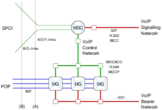
Figure 1 illustrates one network node configuration discussed in the paper SS7 over IP: Signaling Interworking Vulnerabilities from the SS7 network perspective.
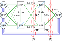
Figure 1 shows two typical demarcation points for interconnection. A Point-of-Presence (POP) occurs at the facilities between interconnected SSPs. The precise POP demarcation point is largely arbitrary as far as security is concerned. A Signalling Point of Interface (SPOI) occurs either across the B/D-Links interconnecting STP associated pairs (indicated by dotted line (B)), or across the A/E-Links interconnecting the SSP to the SS7 network (indicated by dotted line (A)).
The SSP on the right of Figure 1 can be further decomposed according to the SIGTRAN and TIPHON architectures as illustrated in Figure 2 and Figure 3. The SIGTRAN architecture provides for two forms of decomposition and back-haul of SS7 signalling traffic over an IP network. Each form corresponds to the demarcation points and interconnect strategies illustrated in Figure 1.
The TIPHON architecture provides for decomposition of a gateway appearing as an SSP within the SS7 network that provides interworking between the traditional ISUP based call control of the SS7 network and the BICC, H.323 or SIP call control of a VoIP network.
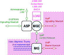
The gateway is decomposed into three (3) roles: the Media Gateway Controller (MGC) that provides call control interworking between ISUP and BICC, H.323 or SIP; the Signalling Gateway (SG) that provides signalling interworking and distribution within the decomposed gateway; and, the Media Gateway (MG) the provides media conversion between TDM bearer channels in the Switched Circuit Network (SCN) and Real-Time Transport Protocol (RTP) sessions in the VoIP network. This decomposition is the same independent of the demarcation point or interconnect strategy and is illustrated in both Figure 2 and Figure 3.
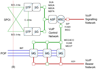
As illustrated in Figure 2, the SIGTRAN decomposition of the SSP at interconnection point (B) utilizes a pair of Signalling Gateways (SGs) that act as an associated pair of Signalling Transfer Points (STPs) to the SS7 network. The Media Gateway Controller (MGC) provides SSP call control functions and acts as an ASP toward the SGs within the SIGTRAN network. SUA, M3UA, M2UA or M2PA SIGTRAN protocols can be used.
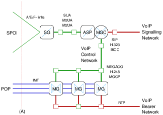
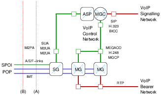
As illustrated in Figure 3, the SIGTRAN decomposition of the SSP at interconnection point (A) utilizes a single Signalling Gateway (SG) that acts as a signalling end point (SEP) to the SS7 network. The Media Gateway Controller (MGC) provides SSP call control functions and acts as an ASP toward the SG within the SIGTRAN network. SUA, M3UA, M2UA (but not M2PA) SIGTRAN protocols can be used.
Typically, the networks labelled as VoIP Control Network in Figure 2 and Figure 3 is a secured private network. Although the networks labelled as VoIP Signalling Network and VoIP Bearer Network might be directly or indirectly connected to the public Internet, they likely are not in real-world deployments. Normally a BICC gateway (GW), H.323 Gate Keeper (GK) or SIP Proxy would stand between the VoIP Signalling Network and a public Internet or even a private network attached ultimately to a public Internet. Normally a Network Address Translation (NAT) device, IP Proxy, IP Firewall and security routers would stand, both between the SIGTRAN Signalling Network and VoIP Control Network and any external attached network elements, as well as between the MGC and the VoIP Signalling Network and the MGs and the VoIP Bearer Network.
Nevertheless, the objective of the SS7/SIGTRAN/VoIP Security Network is to provide experiment access to each node and control or signalling network in the system.
2.2 Experimental Approach
The experimental approach is to provide a network environment that behaves much the same as the Public Switched Telephone Network (PSTN) in regard to the processing of calls and the functional platforms and logical nodes provided. Commercial implementations of protocols and call processing functions will be used throughout. The SS7/SIGTRAN/VoIP Security Network is a captive network in the sense that it is not connected to the Public Switched Telephone Network (PTSN) nor Public Internet. Each node in the captive network will be fully instrumented for the purpose of running experiments. The captive network will carry a high volume of call traffic in the same manner as a typical medium scale deployment within the PSTN. Call traffic will be generated using best practise load generation techniques (load box) normally used for testing the performance and capacity of telecommunications networks.2 Experiments will then be run against this operating system in attempting to attack the system using the techniques documented in the paper: SS7 over IP: Signaling Interworking Vulnerabilities.
2.3 Experiment Requirements
In support of experimentation with signalling security, the following high-level requirements arise:
- The system should as closely as possible provide the configuration and capabilities found in a medium to large scale public network.
- The system must be able to sustain a high signalling load while performing experiments.
- Call traffic generators and acceptors will be provided to simulate the call traffic load of many subscribers in a large network.
- The system will be instrumented and call traffic monitors and audits provided for correct completion and release of each call. This is to assist in the determination of the results of a given experiment.3
The following efficiencies will be exploited:
- As the actual bearer channels are not the subject of current investigation4, an efficiency can be gained by not physically providing the Inter-Machine Trunks (IMTs), Media Gateways (MGs) or RTP channels necessary to provide the bearer capabilities for the generated traffic.
- Intra-switch traffic does not need to be generated; only inter-switch traffic. Because intra-switch traffic (some 80% of the call traffic experienced within the PSTN) does not expose itself as ISUP SS7 signalling, it need not be simulated. By not simulating intra-switch traffic, a PSTN environment of five (5) times the scale or more can be accomplished with the same capacity of equipment.
- PSTN line-side interfaces and devices5 do not need to be provided. Traffic generation and acceptance can be simulated with direct ISUP traffic generation and acceptance.
- VoIP network User Agent (UAs), the equivalent of PSTN line-side devices, do not need to be provided for signalling security testing. In a later phase, these devices could be simulated.
- ISUP protocol stacks provide a set of standard operational measurements that can be used to
instrument and monitor call completion and release. Operations measurements include the number of
lost or abnormal calls, including the nature of the failure and diagnostic information. This
information will be reused to instrument ISUP call processing within the network in several
ways:
- Operational measurement statistics can be used to show the impact of an experiment on the ability of the system to function normally. Operational measurement statistics are an indicator of the health of the system and are collected on an ongoing basis for all nodes.
- Operational measurement studies6 can be defined to report the impact of specific experiments.
- Operational measurement alarms can be collected and used to indicate the level of maintenance and security response by an operator to experiments.
- Call processing logic in commercial PSTN SSPs provide for authentication, authorization, screening and verification of call signalling information for the purposes of telecommunications network security. This authentication, authorization, screening and verification is aimed at providing security of telecommunications common equipment resources and billing audit and verification. These processes are sophisticated and have evolved from a long history of attempted and successful abuse of the public telephone network. However, these methods are not the focus of an investigation into the security of signalling systems and will not be implemented on load generated traffic.
- In actual deployments, network elements occur at a geographic distance and short and long haul telecommunications facilities connect the network elements. For the purposes of signalling security, the distance between nodes and the facilities between them are not a focus. All connecting facilities, although of the same type as found in real networks, will be intra-office facilities and within the system will be cage to cage connections not exceeding several meters.
- In network deployments there is a high degree of physical security surrounding primary network elements such as LEC primary STPs. In these installations, simply opening a door can generate security alarms. For the purpose of signalling security testing, this physical security will not be recreated.
3 Network Configuration
To satisfy the requirements for experimentation with the security of the SS7/SIGTRAN/VoIP Security Network, the intention is for the instrumentation to provide a telecommunications network and environment that parallels actual Local Exchange Carrier (LEC) deployments within the Public Switched Telephone Network (PSTN). The SS7/SIGTRAN/VoIP Security Network will provide a captive network equivalent to the PSTN in which experiments can be performed and meaningful results collected. To accomplish this, the logical nodes in the SS7/SIGTRAN/VoIP Security Network provide the capabilities of typical physical nodes, platforms and installations in the PSTN.
The mapping of logical PSTN and VoIP network elements onto the physical nodes of the captive network is the subject of this section. First the logical network configuration is determined, and then the mapping of logical network configuration onto a physical realization is provided.
3.1 Logical Network Configuration
In this section the types of logical network elements (nodes) and their typical interconnection and configuration is discussed. The number of logical nodes of each type and a single captive network configuration suitable for the purposes of experimentation in signalling system security is then proposed.
3.1.1 Logical Network Nodes
To meet the requirements of PSTN experimentation, the logical nodes that need to be provided are as follows:
3.1.1.1 Service Switching Point (SSP)
Service switching points (SSPs) are Switches (end-offices, tandem, toll) within the PSTN under the SS7 signalling architecture. These node initiate and terminate ISUP call connections.
SS7 signalling links (A/F-links) connect SSP to STP within the PSTN. Service switching points within the PSTN also terminate voice circuits for ISUP call connections.
Each physical node within the SS7/SIGTRAN/VoIP Security Network is capable of providing multiple logical SSPs, each with their own set of SS7 signalling links (A/F-links) connected into the SS7 signalling network, and each with their own ISUP circuit connections. For the purposes of signalling security experimentation, it is not necessary to provide circuit connections for ISUP call bearer circuits.
Operational measurements that are available for experiment result analysis are the complete set of standard MTP and ISUP statistics and events as indicated in ITU-T Recommendation Q.7527.
3.1.1.2 Signalling Transfer Point (STP)
Signalling transfer points (STPs) are signalling relay points within the PSTN under the SS7 signalling architecture. These nodes neither initiate nor terminate ISUP call connections, but transfer the signalling messages between SSPs that do.
SS7 signalling links (A/F-links) connect SSP to STP within the PSTN. STPs are also connected to other STPs using SS7 signalling links (B/C/D-links). B/D-links are used to connect STPs together along the signalling transfer path. C-links (or cross-links) are used to connected mated pairs of STPs together to form redundant pairs of STPs.
Each physical node within the SS7/SIGTRAN/VoIP Security Network is capable of providing multiple logical STPs, each with their own set of SS7 signalling links (B/C/D-links) connected into the SS7 signalling network.
Operational measurements that are available for experiment result analysis are the complete set of standard MTP statistics and events as indicated in ITU-T Recommendation Q.7528.
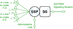
3.1.1.3 Signalling Gateway (SG)
Signalling gateways (SGs) are interworking points to the PSTN under the SIGTRAN signalling architecture. These nodes neither initiate nor terminate ISUP call connections, but transfer and inter-work signalling messages between the SS7 signalling network and the SIGTRAN IP network.
Signalling gateways (with the sole exception of M2PA) connect to the SS7 network using traditional SS7 signalling links and connect to the IP network using typical network interfaces (e.g. Ethernet). Signalling gateways do not terminate ISUP call circuits within the SIGTRAN architecture.
Two types of signalling gateways are possible, distinguished by how the node appears logically within the SS7 networks:
- SG as SSP. When a signalling gateway appears within the SS7 network as a service switching point (SSP), the signalling gateway terminates A/F-links (SS7 signalling links) and presents the signalling point code of a service switching point.
- SG as STP. When a signalling gateway appears within the SS7 network as a signalling transfer point (STP), the signalling gateway terminates B/C/D-links (SS7 signalling links), are normally provisioned in mated pairs, and present the signalling point code of a signalling transfer point (STP) and proxy virtual signalling points (VSP) which are an emulated of A/F-link attached SSPs.
Each physical node with the SS7/SIGTRAN/VoIP Security Network is capable of providing multiple logical SGs of either type, each with their own set of SS7 signalling links (A/B/C/D/E/F-links) and network interfaces or SCTP connections to the Internet Protocol network.
Operational measurements that are available for experiment result analysis are the complete set of standard MTP statistics and events as indicated in ITU-T Recommendation Q.7529. There are no standard MIBs available for SIGTRAN protocols other than SCTP itself.
3.1.1.4 Application Server Process (ASP)
Application server processes (ASPs) are interworking points to the PSTN under the SIGTRAN signalling architecture. These nodes may initiate or terminate ISUP call connections.
Network interfaces (such as Ethernet) are used to connect ASPs to the SIGTRAN IP network, and ASPs may terminate ISUP call bearer circuits. ASPs do not have SS7 signalling links.
Each physical node within the SS7/SIGTRAN/VoIP Security Network is capable of providing multiple logical ASPs, each with their own set of network interfaces or SCTP connections to the Internet Protocol network, and each with their own set of ISUP call bearer circuits.
Operational measurements that are available for experiment result analysis are the complete set of standard MTP and ISUP statistics and events as indicated in ITU-T Recommendation Q.75210. There are no standard MIBs available for SIGTRAN protocols other than SCTP itself.
3.1.1.5 Media Gateway Controller (MGC)
Media gateway controllers (MGCs) are interworking points to the PSTN under the ETSI TIPHON architecture. These nodes neither initiate nor terminate ISUP call connections, but inter-work then to SIP or H.323 calls external to the PSTN.
Media gateway controllers connect to the SS7 network using traditional SS7 signalling links (normally A/F-links) and act like an tandem SSP (non-end-office) within the PSTN. Media gateway controls connect to the Internet Protocol network using network interfaces and form TCP or SCTP connections within that network. Media gateway controllers connect to Media Gateways (MGs) using network interfaces and form TCP or SCTP connections within that network. Media gateway controllers neither terminate ISUP call bearer circuits nor RTP sessions.
Each physical node within the SS7/SIGTRAN/VoIP Security Network is capable of providing multiple logical MGCs, each with their own set of SS7 signalling links and IP network interfaces or TCP/SCTP connections.
Operational measurements that are available for experiment result analysis are the complete set of standard MTP and ISUP statistics and events as indicated in ITU-T Recommendation Q.75211.
3.1.1.6 Media Gateway (MG)
Media gateway controllers (MGs) are bearer channel inter-working points to the PSTN under the ETSI TIPHON architecture. These nodes neither initiate not terminate ISUP call connections, but inter-work between the TDM-based ISUP call bearer circuits in the PSTN and ephemeral RTP sessions within the IP network.
Although each physical SS7/SIGTRAN/VoIP Security Network node is capable of providing multiple logical MG functions, this function is not necessary to the investigation of signalling security.
3.1.2 Logical Node Configuration
To satisfy the requirements for experimentation, the proposed logical node configuration is chosen to provide as many characteristics experienced in a real interconnect arrangement as possible, while limiting the interworking points to a few specific locations within the captive network for the purpose of monitoring and collection of results of experimentation.
3.1.2.1 SS7 Network Configuration
Figure 4 illustrates the typical network node configuration under the SS7 network architecture:
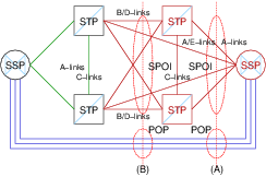
Figure 4 shows the types of nodes within the SS7/SIGTRAN/VoIP Security Network, and an indication of the number of nodes within each type. There are four types of nodes:
LEC service switching points (SSPs).
For the purposes of security experimentation, more than one logical LEC SSP will be provided. The purpose of providing multiple LEC SSPs is to be able to monitor any description of call traffic between LEC SSP nodes.
In normal CO arrangements, LEC SSP call control is not connected to any publicly accessible IP network (full air gap). The only manner in which attackers (and thus realistic experiments) can affect the operation of LEC SSPs is via the SS7 protocol. Physical security of SSPs should be considered separate from signalling system security.
Each LEC SSP is capable of providing varying degrees of screening on ISUP signalling on an trunk group by trunk group basis. Whether a call is routed or billed correctly depends upon LEC security screening policy and policies with regards to software standards, translations, customer data fill, MATELs and RCOs. These aspects should be considered as separate from signalling system security.
LEC signalling transfer points (STPs).
For the purpose of security experimentation, one logical associated pair of LEC STPs will be provided. Providing only one pair is consistent with the interconnect topology of relatively large LEC networks.
In normal CO arrangements, LEC STPs are not connected to any publicly accessible IP network (full air gap). The only manner in which attackers (and thus realistic experiments) can affect the operation of the LEC STP is via the SS7 protocol. Physical security of STPs is, in practise, quite high, and should be considered separate from signalling system security.
Each LEC STP is capable of providing Enhanced and Border Gateway Screening (EGWS/BGWS) applied on any or all attached SS7 links. In real networks, any STP associated pair to which an external administration interconnects is so equipped and full screening is activated.
IC signalling transfer points (STPs).
For the purpose of security experimentation, one logical associated pair of IC STPs will be provided. Providing only one pair is consistent with the interconnect topology of relatively large IC (e.g. IXCs).
In normal CO arrangements, interconnects employ similar security policies to that of the LEC, a situation that is required for under FCC regulation. It is not reasonable to assume that the IC STPs are any more subject to IP network attack than the LEC STPs. It can be assumed that they are not attached (full air gap) to any publicly accessible IP network and that the only way that their behaviour can be affected is via SS7 signalling links.
Each IC STP is capable of providing Enhanced and Border Gateway Screening (EGWS/BGWS) applied on any or all attached SS7 links. In real networks, any STP associated pair to which an external administration interconnects is so equipped and full screening is activated.
IC service switching points (SSPs).
For the purpose of security experimentation, only one logical IC SSP need be provided.
The particular IC SSPs of concern to the current investigations are SSPs that are decomposed into IETF SIGTRAN and ETSI TIPHON components as described under SIGTRAN Network Configuration and TIPHON Network Configuration, below.
3.1.2.2 TIPHON Network Configuration
Figure 5 illustrates the typical network node configuration under the TIPHON network architecture.
The ETSI TIPHON VoIP architecture decomposes the IC SSP in Figure 4 into the components illustrated in Figure 5. The components are as follows:
Media Gateway Controller (MGC)
The media gateway controller (MGC) is responsible for terminating call control signalling within both the SCN (Switched Circuit Network) and the IP Network and providing interworking between the protocols. In some instances this interworking might be rather trivial (as in the case of ISUP and BICC, or Q.931 and H.245) or complex (as in the case of ISUP and SIP).
Media Gateway (MG)
The media gateway (MG) is responsible for conversion of TDM bearer channels and Real-Time Transport (RTP) Audio-Video Profile (AVP) sessions. The conversion is performed under the control of the Media Gateway Controller (MGC) using a media gateway control protocol such as MEGACO/H.248 or MGCP.
Signalling Gateway (SG)
The signalling gateway (SG) is responsible for conversion of TDM signalling access to an internal signalling representation usable by the Media Gateway Controller (MGC). The signalling gateway (SG) is a functional component and is often integrated on the same platform as the MGC or MG.
3.1.2.3 SIGTRAN Network Configuration
Figure 6 illustrates the typical network node configuration under the SIGTRAN network architecture.
3.1.3 Proposed Logical Nodes
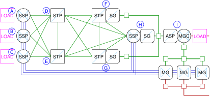
In fitting with diagrams Figure 4, Figure 5 and Figure 6, 9 logical nodes will be provided as follows:
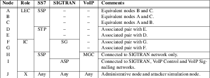
As listed in Table T-1, logical nodes A, B and C are LEC SSPs that are interconnected to each other as well as to the IC SSP/MGC (node I). Nodes D and E are LEC STPs that form the LEC SS7 backbone network. Nodes F and G are optional IC STP/SGs. Node H is an SSP/SG within the SIGTRAN network behaving like an SSP. Node I is an MGC/ASP acting as a gateway to the VoIP network. Node J (not shown in the diagrams) is an purely administrative node acting in the role of an OSS (Operational Support System).
The proposed logical node network configuration is illustrated in Figure 7.
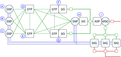
Note that in Figure 7, only the signalling components are fully implemented. The Inter-Machine Trunks (IMTs) shown in blue connecting SSP components are not implemented to reduce expense. Also, the Media Gateways (MGs) shown are not implemented, the VoIP Control Network between the MGC and the MGs is not implemented, and the RTP network from the MGs is not implemented.
3.2 Physical Network Configuration
Each physical node within the SS7/SIGTRAN/VoIP Security Network consists of a high-performance commodity computing platform, specialized TDM interface cards for providing narrow-band and high-speed SS7 signalling links and narrow-band ISUP call bearer circuits, as well as network interfaces (Ethernet) to the IP network.
Each physical node within the SS7/SIGTRAN/VoIP Security Network can acts as multiple logical nodes within the SS7, SIGTRAN or VoIP architectures. Logical nodes are assigned dedicated circuit facilities from TDM interfaces as well as forming dedicated TCP or SCTP connections over the IP network.
Configuration of the network operating environment consists of the mapping of logical nodes onto physical nodes and the interconnection of the physical nodes.
3.2.1 Logical Node Mapping Alternatives
There are several alternatives for mechanisms used for the mapping of logical nodes onto physical compute platforms, referred to here as virtualization and non-virtualization approaches as follows:
Virtualization
Under a virtualization approach, the machine virtualization provided by the Xen Hypervisor allow one physical compute platform to run multiple operating system kernels. Under this approach, each logical node would run on a different instance of the Linux operating system running under the hypervisor.
The advantage of this approach for the investigation of stack security is that if the operating system can be caused to crash, it will only affect one logical node and not all logical nodes operating on the physical platform. This has advantages in maintaining independence between logical nodes. The disadvantage is configuration complexity.
Non-Virtualization
Under a non-virtualization approach, the machine runs a single Linux operating system. Under this approach, each logical node would run as a set of processes on one instance of the Linux operating system running native on the machine.
The advantage of this approach is simplicity. The disadvantage of this approach for the investigation of stack security is that, if the operating system can be caused to crash, all logical nodes will be affected.
Because the OpenSS7 stacks have been designed to provide partitioned logical nodes in a non-virtualization environment, the non-virtualization approach will be take at least initially. If the need arises, the virtualization approach can be assumed at a later date.
3.2.2 Logical Nodes versus Physical Nodes
Although the entire SS7/SIGTRAN/VoIP Security Network could be implemented on so little as a single compute platform, the objectives of experimentation with signalling system security is better met by multiple physical compute platforms for the following reasons:
Signalling Capacity
It is not possible for the SS7/SIGTRAN/VoIP Securty Network to approach the signalling capacity of even small PSTN LEC networks with a single compute platform. Without large signalling capacity it is difficult to extrapolate from experimental results to the impact on large scale call handling. With a high-performance system providing the signalling capacity of a large LEC network, experimental results are directly applicable to real-world networks.
Node Independence
Although logical nodes can be defined so that more than one logical node exists on a given physical compute platform, doing so creates a dependence between the logical nodes that exists, even if the virtualization approach is taken.12 It could be argued that experimental results impacting a network run on a single physical compute platform would have less of an impact on networks composed of independent platforms.
Node Isolation
By placing logical nodes that are normally isolated from a public IP network by an air gap with logical nodes not so isolated from a public IP network, it might be tempting to show experimental results where one node affects the other directly through programmatic interfaces on the same machine rather than via the external interfaces normally associated with such a logical node on the network.
For example, a LEC STP that is separated from an IP network by an air gap running on the same compute platform as, say, an MGC that is, perhaps, indirectly connected to a public IP network, would permit an experiment to use programmatic interfaces to the STP on the same platform as the MGC. It could be argued that the results of such an experiment are not applicable to real-world networks.
Security
Physical platforms that have a narrow defined purpose are easier to secure than those that have a broad purpose. If multiple logical nodes are implemented on the same physical compute platform, it could be argued that the experiment results would not be applicable to a real-world telecommunications platform that exists with a very narrow defined scope (such as an STP).
Nevertheless, small systems can be built using a single compute platform for purposes such as the independent development of experiments.
4 Instrumentation
The SS7/SIGTRAN/VoIP Security Network will have three categories of instrumentation for the purpose of execution of experiments against the network:
- Traffic Generation.
Traffic generation provides the ability to determine the impact of specific experiments on the operation of large networks and specifically the processing of ISUP calls.
- Operational Measurements.
Operational measurements provide statistics, event and alarm detection and collection that can be used to analyze the results of specific experiments on the operation of large networks.
- Distributed Test Harness.
A distributed test harness provides a repeatable framework within which to generate and operation specific experiments.
4.1 Traffic Generation
To meet the purposes of providing an SS7/SIGTRAN/VoIP Security Network that parallels that found in actual deployments within the PSTN, generation of network signalling traffic at levels comparable to a LEC network is required. To accomplish this, logical nodes terminating ISUP traffic will be equipped with virtual traffic load generators (i.e. load boxes) in the same physical node.
Traffic loading points are illustrated in Figure 8.
There are four traffic load generation points within the SS7/SIGTRAN/VoIP Security Network: three (3) load generation points, one each at each of the LEC SSPs (nodes A, B, C) in the network configuration as illustrated in Figure 8; and one (1) load generation point at the IC MGC (node I).
The characteristics of the traffic load generators are as follows:
- Each traffic load generator will generate ISUP call traffic for a specific number of subscriber lines. Suggested distribution of subscriber lines are 25% of the overall number of subscriber lines for each of the SSP and MGC traffic generation points. A target figure is to generate signalling traffic for ten million (10,000,000) overall subscriber lines (four million BHCA, or 288 million call minutes per day).
- Each subscriber line will be modelled as a pure birth-death process providing between 4-8 CCS (Centi Call Seconds) of average day peak hour load. An average holding time of 3-5 minutes will be used.13
- Of this load, 80% will be considered intra-switch and will not be generated. 20% will be considered inter-switch and will be generated. Splitting of intra-switch and inter-switch traffic will be done using determinate load splitting of Poisson distributed traffic.
- Distribution of calls over the available subscriber lines will be performed considering a fixed and equal probability of a call being generated between any given subscriber line and any other subscriber line.
- Busy treatment patterns will be simulated. Subscriber line busy treatment will be based on actual subscriber line status. 60% of the subscriber lines will be considered as equipped with a busy/no-answer treatment that results in call connection (i.e. voice mail, CFBNA). Calls that would otherwise encounter busy treatment (according to actual line status) will be considered to be abandoned without reattempt if the terminating line is not equipped with a CFB service. When equipped with a CFB service the call will be considered to hold for only 30-60 seconds.
- No-answer treatment patterns will be simulated. Subscriber line no-answer treatment will be considered on a fixed and equal probability. Lines considered as having no-answer but equipped with a no-answer service (60% of the lines) will be considered to hold for only 30-60 seconds.
- All trunks busy treatment patterns will be actual. Inter-office trunk groups will be engineered for the experienced traffic rates at an Erlang C blocking probability of 0.999 for high-day busy hour. This is consistent with toll grade trunks traffic engineering. As the traffic is simulated for average-day busy hour, trunk blocking probability is almost zero. Therefore, for the purpose of simplifying the simulation, all trunks busy treatment will be be applied.
4.2 Operational Measurements
Each SS7 node in the SS7/SIGTRAN/VoIP Security Network provides full operational measurements in accordance with ITU-T Recommendation Q.752. This recommendations provides for both basic statistics collection and basic alarm generation.
4.2.1 MTP Operational Measurements
Each logical node providing an MTP layer will provide complete Q.752 operational measurements for the MTP layers it provides. In the proposed SS7/SIGTRAN/ISUP Security Network logical nodes (see Proposed Logical Nodes), all logical nodes with the possible exception of the MGC/ASP node (node ‘I’)14, provide some portion of the MTP layer and will provide operational measurements, statistical collection and alarm generation.
Operational measurements for MTP listed in Q.752 are as follows:
MTP Signalling link faults and performance.
| 1.1 | Duration of link in the in-service state. |
| 1.2 | Signalling link failure, all reasons. |
| 1.3 | Signalling link failure, abnormal FIBR/BSNR. |
| 1.4 | Signalling link failure, excessive delay of acknowledgement. |
| 1.5 | Signalling link failure, excessive error rate. |
| 1.6 | Signalling link failure, excessive duration of congestion. |
| 1.7 | Signalling link alignment or proving failure. |
| 1.8 | Number of signal units received in error. |
| 1.9 | Number of negative acknowledgements received. |
| 1.10 | Local automatic changeover. |
| 1.11 | Local automatic changeback. |
| 1.12 | Signalling link restoration. |
MTP signalling link availability.
| 2.1 | Duration of signalling link unavailability, for any reason. |
| 2.5 | Duration of signalling link inhibition, local management actions. |
| 2.6 | Duration of signalling link inhibition, remote management actions. |
| 2.7 | Duration of signalling link unavailability, link failure. |
| 2.9 | Duration of signalling link unavailability, remote processor outage. |
| 2.10 | Start of remote processor outage. |
| 2.11 | Stop of remote processor outage. |
| 2.13 | Local management inhibit. |
| 2.14 | Local management uninhibit. |
| 2.15 | Duration of local busy. |
| 2.16 | Start of local inhibition. |
| 2.17 | End of local inhibition. |
| 2.18 | Start of remote inhibition. |
| 2.19 | End of remote inhibition. |
MTP signalling link utilization.
| 3.1 | Number of SIF and SIO octets transmitted. |
| 3.2 | Octets retransmitted. |
| 3.3 | Number of message signal units transmitted. |
| 3.4 | Number of SIF and SIO octets received. |
| 3.5 | Number of message signal units received. |
| 3.6 | Signalling link congestion indications. |
| 3.7 | Cumulative duration of signalling link congestion. |
| 3.10 | MSUs discarded, signalling link congestion. |
| 3.11 | Number of congestion events resulting in loss of MSUs. |
MTP signalling link set and route set availability.
| 4.2 | Duration of unavailability of signalling link set. |
| 4.3 | Start of link set failure. |
| 4.4 | Stop of link set failure. |
| 4.5 | Initiation of broadcast TFP, failure of measured link set. |
| 4.6 | Initiation of broadcast TFA for recovery of measured link set. |
| 4.9 | Unavailability of route set to a given destination (set). |
| 4.10 | Duration of unavailability of a route set to a given destination (set). |
| 4.11 | Start of unavailability of a route set to a given destination (set). |
| 4.12 | Stop of unavailability of a route set to a given destination (set). |
| 4.13 | Change in link set used to adjacent SP. |
MTP signalling point status.
| 5.1 | Adjacent SP inaccessible. |
| 5.2 | Duration of adjacent SP inaccessible. |
| 5.4 | Stop of adjacent SP inaccessible. |
| 5.5 | MSU discarded, routing data error. |
| 5.6 | User Part Unavailable MSU transmitted. |
| 5.7 | User Part Unavailable MSU received. |
| 5.8 | TFC received. |
MTP signalling traffic distribution (signalling route utilization).
| 6.1 | Number of SIF and SIO octets received with given OPC (set) at an SEP. |
| 6.2 | Number of SIF and SIO octets transmitted with given DPC (set) at an SEP. |
| 6.3 | Number of SIF and SIO octets handled with given SI (set) at an STP. |
| 6.4 | Number of SIF and SIO octets received with given OPC (set) at an SEP. |
| 6.5 | Number of SIF and SIO octets transmitted with given DPC (set) at an SEP. |
| 6.6 | Number of SIF and SIO octets handled with given OPC set, DPC set and SI set, at an STP. |
| 6.7 | Number of MSUs handled with given OPC set, DPC set and SI set, at an STP. |
Operational measurements that collect statistics over a time period may have high or low water mark thresholds set to generate alarms. Operational measurements marked as on-occurrence or first-and-delta may also generate alarms. In addition to these operational measurements, events within the MTP protocol providing for management events can also generate alarms.
4.2.2 ISUP Operational Measurements
Each logical node providing an ISUP layer will provide complete Q.752 operational measurements for the ISUP layer it provides. In the proposed SS7/SIGTRAN/ISUP Security Network logical nodes (see Proposed Logical Nodes), only the LEC SSPs (nodes ‘A’, ‘B’, ‘C’) and IC MGC (node ‘I’) provide an ISUP layer. These coincide with ISUP traffic generation points (see Figure 8).
Operational measurements for ISUP listed in Q.752 are as follows:
ISDN User Part availability.
| 10.1 | Start of local ISUP unavailable, failure. |
| 10.2 | Start of local ISUP unavailable, maintenance made busy. |
| 10.3 | ISUP available. |
| 10.4 | Total duration ISUP available. |
| 10.5 | Start of local ISUP congestion. |
| 10.6 | Stop of local ISUP congestion. |
| 10.7 | Duration of local ISUP congestion. |
| 10.8 | Start of remote ISUP unavailable. |
| 10.9 | Stop of remote ISUP unavailable. |
| 10.10 | Duration of remote ISUP unavailable. |
| 10.11 | Start of remote ISUP congestion. |
| 10.12 | Stop of remote ISUP congestion. |
| 10.13 | Duration of remote ISUP congestion. |
ISDN User Part utilization.
| 11.1 | Total ISUP messages sent. |
| 11.2 | Total ISUP messages received. |
ISDN User Part errors.
| 12.1 | No acknowledgement for circuit reset within T17. |
| 12.2 | No GRA received for GRS within T23. |
| 12.5 | RLC not received within T5. |
| 12.6 | Release initiated due to abnormal conditions. |
| 12.7 | Circuit BLO (excessive errors detected by CRC). |
| 12.8 | Missing blocking acknowledgement in CGBA for previous CGB. |
| 12.9 | Missing unblocking acknowledgement in CGUA for previous CGU. |
| 12.10 | Abnormal blocking acknowledgement in CGBA for previous CGB. |
| 12.11 | Abnormal blocking acknowledgement in CGUA for previous CGU. |
| 12.12 | Unexpected CGBA with abnormal blocking acknowledgement. |
| 12.13 | Unexpected CGUA with abnormal unblocking acknowledgement. |
| 12.14 | Unexpected BLA with abnormal blocking acknowledgement. |
| 12.15 | Unexpected UBA with abnormal unblocking acknowledgement. |
| 12.16 | No BLA received for BLO within T13. |
| 12.17 | No UBA received for UBL within T15. |
| 12.18 | No CGBA received for CGB within T19. |
| 12.19 | No CGUA received for CGU within T21. |
| 12.20 | Message format error. |
| 12.21 | Unexpected message received. |
| 12.22 | Release due to unrecognized information. |
| 12.23 | Inability to release a circuit. |
Operational measurements that collect statistics over a time period may have high or low water mark thresholds set to generate alarms. Operational measurements marked as on-occurrence or first-and-delta may also generate alarms. In addition to these operational measurements, events within the MTP protocol providing for management events can also generate alarms.
Most switches also perform trunk peg counts and operational measurements on a per-member basis for the purpose of trunk group sizing and traffic engineering.
4.2.3 Special Studies
On most switches, operational measurements associated with the translation process within the switchiing element can also be collected. These operational measurements are based on originating and termination classes of service, class of service screening, trunk group screening, and call treatment. In addition to operational measurements, billing records are generated that contain call detail records on a per-call basis for billable calls. For the purpose of traffic engineering or other traffic studies, it is possible to institute special studies that collect information according to a study criteria. It is also possible to collect call detail records and call traces on a specified criteria. Alarms can be generated on statistics high and low water marks as well as a result of any number of events determined through translations on the switching element. Alarms notify local maintenance personnel with both audible and visual alarms on a LADS (local alarm display system) and are logged locally and remotely. Alarms also notify remote NOC (Network Operations Control) and security systems and personnel.
The SS7/SIGTRAN/VoIP Security Network logical nodes that provide the ISUP call control will also provide the ability to perform special studies related to the load traffic for the purposes of determining the effected of experiments on the system.
4.3 Distributed Test Harness
A distributed test harness will be provided for running experiments on the SS7/SIGTRAN/VoIP Security Network. Each of the logical nodes in the system will be equipped with and run a network distributed copy of the TETWare 3.3h distributed test system available from the OpenGroup.
On logical nodes equipped with ISUP and subscriber call load generation (nodes A, B, C, I), TETWare will provide access to the MTP and ISUP operational measurements, alarms, maintenance logs, special studies and other call completion information for collecting and reporting the impact on call processing of various experiments. On the remaining logical nodes providing only SS7/SIGTRAN capabilities (nodes D, E, F, G, H), TETWare will provide access to the MTP operational measurements, alarms, maintenance logs, and other SS7 system information for collecting and reporting the impact on SS7 signalling of various experiments.
On both sets of logical nodes (nodes A through I, but not J), TETWare will provide a scripting and ‘C’-language execution environment for the execution of experiments. The administrative node (node J) is responsible for providing access to the entire SS7/SIGTRAN/VoIP Security Network for the synchronization and coordination of experiments.
Experiments will typcially componsed of the following:
- Hypothetical Attack Script.
The hypothetical attack script corresponds to a test case within the TETWware framework and provides a mechanism for executing an experiment against a specific logical node in the SS7/SIGTRAN/VoIP Security Network.
- Call processing monitors.
Call processing monitors collect information from operational measurements and studies on the operation of call processing to provide a results report on the impact of the experiment for the purposes of report generation.
- SS7 signalling monitors.
SS7 signalling monitors collect information from operational measurements on the operation of SS7 signalling to provide a results report on the impact of the experiment for the purposes of report generation.
4.3.1 Hypothetical Attack Script
A hypothetical attack script is the portion of an experiment that represents an executable that has been invoked by an attacker of the system.
Attack scripts can be run on any node in the system under the TETWare server running on each node. When run on a node in the system (except node J), it is presumed that the node has somehow been compromised and that some level of access has been afforded the attacker. When run on node J, it is presumed that the attack is being launched from an machine external to the system.
As they are not connected to a public IP network (i.e. they are separated from public networks by an air gap), it is not a valid assumption that nodes A, B, C, D and E are compromised and experiments that execute attack scripts on these nodes are of no value.
Although they are attached via IP based networks other than the administrative LAN, due to the specialized nature of the interconnecting SIGTRAN network, it is a weak assumption that nodes F, G and H are compromised and experiments that execute attack scripts on these nodes are of low value.
Node I is directly or indirectly attached to a public IP network. As a result, it could be considered compromised if adequate security procedures are not assumed. Therefore, attack scripts executed on nodes I or J are of the greatest value.
4.3.2 Call Processing Monitors
Monitoring of call processing with operational measurements statistics collection, event reporting, alarm generation, logging and special studies will be integrated into TETWare to provide for report generation of experiment (test case) results on systems running ISUP traffic generators (logical nodes A, B, C and H).
4.3.3 SS7 Signalling Monitors
5 Node Configuration
Node configuration is separated for discussion into logical and physical nodes:
Logical Nodes
Logical nodes represent a functional grouping of SS7 network element capabilities into a logical network element that is normally deployed separately within the SS7 network.
Physical Nodes
Physical nodes represent a separate and distinct computing platform and the associated network interfaces that are used by logical network elements assigned to the physical platform.
5.1 Logical Nodes
Logical nodes provide for functional grouping of network element capabilities into a virtual network element that is independent of the executional platform on which the virtual network element executes.
This section details the configuration of the following logical nodes:
- LEC SSP Nodes A, B and C.
- LEC STP Nodes D and E.
- IC STP/SG Nodes F and G.
- IC MGC/SG Node H.
- IC MGC/ASP Node I.
- Administrative Node J.
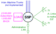
5.1.1 LEC SSP Nodes A, B and C
Interconnection of the LEC SSP Nodes A, B and C are illustrated in Figure N-1.
Overview
| TDM Interface: | 2 T1 spans of SS7 narrow-band signalling links. |
| Network Interface: | Administrative LAN. |
| Protocol Components: | MTP and ISUP. |
| Load Generation: | 2,500,000 subscriber lines, 1,000,000 BHCA. |
| Inter-Machine Trunks: | 3 effective trunk groups of 1,544 T1s each. |
| Op. Measurements: | MTP Q.752 Operational Measurements. |
| ISUP Q.752 Operational Measurements. | |
| Special Studies. | |
| Test Harness: | TETWare Distributed Node |
Description
As listed in Table T-1, logical nodes A, B and C are LEC SSPs that are interconnected to each other (with Inter-Machine Trunks, IMTs) as well as to the IC SSP/MGC (node I). Signalling connections are made between each of nodes A, B and C to each of the LEC STPs (nodes D and E). These nodes have only Administrative LAN connection.
Each node is equipped with an Signalling End Point (SEP) SS7 stack including the Message Transfer Part (MTP) and ISDN User Part (ISUP). Load generation is provided for 2,500,000 subscribers (requiring 250 NXX’s).
Each node requires 2 T1 spans on 1 T400P-SS7 interface card.
Each node has 3 inter-machine trunk groups, one each to the two other LEC SSP nodes and one to the IC MGC. These inter-machine trunks are not implemented (to save on system cost).15 Instead, signalling load generation at equivalent levels is provided.
Line-side signalling protocols are not used. Line-side subscribers are simulated using load generation.
Each node is connected only to the Administrative LAN.
Physical Node Mapping
The preferred physical node mapping for logical nodes A, B and C is to provide a separate physical node for each logical node. However, in a minimal configuration, logical nodes A, B and C could be mapped onto a single physical node equipped with 2 T400P-SS7 interface cards.
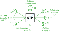
5.1.2 LEC STP Nodes D and E
Interconnection of the LEC STP Nodes D and E are illustrated in Figure N-2.
Overview
| TDM Interface: | 7 T1 spans of SS7 narrow-band signalling links. |
| Network Interface: | Administrative LAN. |
| Protocol Components: | MTP with Enhanced/Border GWS. |
| Load Generation: | None. |
| Inter-Machine Trunks: | None. |
| Op. Measurements: | MTP Q.752 Operational Measurements |
| Test Harness: | TETWare Distributed Node |
Description
As listed in Table T-1, logical nodes D and E are LEC STPs that are interconnected to each other with SS7 C-links, connected to each of nodes F and G with SS7 B/D-links, and connected to node H with A/E-links. Each node D and E are connected to each of LEC SSP nodes A, B and C with SS7 A-links.
Each node requires 7 T1 spans total on 2 T400P-SS7 interface cards.
Each node is connected only to the Adminstrative LAN.
Physical Node Mapping
The preferred physical node mapping for logical nodes D and E is to provide a separate physical node for each logical node. Because each logical node requires 2 T400P-SS7 cards, a minimal configuration still requires one physical node for each logical node for 2U chassis that can only support 2 PCI expansion cards. For server chassis that can support 4 PCI expansion cards, these two logical nodes could be mapped onto a single physical node.
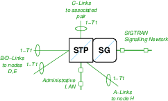
5.1.3 IC STP/SG Nodes F and G
Interconnection of the IC STP/SG Nodes F and G are illustrated in Figure N-3.
Overview
| TDM Interface: | 4 T1 spans of SS7 narrow-band signalling links. |
| Network Interface: | Administrative LAN. |
| SIGTRAN signalling network. | |
| Protocol Components: | MTP, M3UA. |
| Load Generation: | None. |
| Inter-Machine Trunks: | None. |
| Op. Measurements: | MTP Q.752 Operational Measurements |
| Test Harness: | TETWare Distributed Node |
Description
As listed in Table T-1, logical nodes G and F are IC STP/SGs that are interconnected to each other with SS7 C-links, connected to each of nodes D and E with SS7 B/D-links, connected to node H with SS7 A-links, and connected to node H with SIGTRAN M3UA.
Each node requires 4 T1 spans total on 1 T400P-SS7 interface card.
Each node is connected to the Administrative LAN as well as the SIGTRAN Signalling Network. The SIGTRAN Signalling Network includes the associated pair SG as well as the SG node H and the ASP node I. Each of these SG nodes provide access to the ASP node I.
Physical Node Mapping
The preferred physical node mapping for logical nodes F and G is to provide a separate physical node for each logical node. As a minimal system, these logical nodes could be mapped onto a single physical node. For server chassis that can support 3 PCI expansion cards, logical node H could also be mapped onto the same physical node.
5.1.4 IC MGC/SG Node H
Interconnection of the IC SSP/SG Node H is illustrated in Figure N-4.
Overview
| TDM Interface: | 4 T1 spans of SS7 narrow-band signalling links. |
| Network Interface: | Administrative LAN. |
| SIGTRAN signalling network. | |
| Protocol Components: | MTP, M2PA, M2UA, and M3UA. |
| Load Generation: | None. |
| Inter-Machine Trunks: | None. |
| Op. Measurements: | MTP Q.752 Operational Measurements |
| Test Harness: | TETWare Distributed Node |
Description
As listed in Table T-1, logical node H is an IC SSP/SG that is interconnected to each of nodes D and E with SS7 E-links and each of nodes F and G with SS7 A-links.
The node requires 4 T1 spans total on 1 T400P-SS7 interface card.
The node is connected to the Administrative LAN as well as the SIGTRAN Signalling Network.
The SIGTRAN Signalling Network includes the associated pair of SGs (nodes F and G) as well as the ASP node I. Using M2UA or M3UA, this SG node provides access to the ASP node I. Using M2PA, the SG node is connected to M2PA peer SG nodes F and G.
Physical Node Mapping
The preferred physical node mapping for logical node H is to provide a separate physical node for the logical node. As a minimal system, when server chassis can support 3 PCI expansion cards, logical node H could be mapped onto the same physical node as logical nodes F and G.
5.1.5 IC MGC/ASP Node I
Interconnection of the IC MGC/ASP Node I is illustrated in Figure N-5.
Overview
| TDM Interface: | None. |
| Network Interface: | Administrative LAN. |
| SIGTRAN signalling network. | |
| VoIP control network. | |
| VoIP signalling network. | |
| Protocol Components: | MTP, ISUP, M2PA, M2UA, and M3UA. |
| Load Generation: | 2,500,000 subscriber lines. |
| Inter-Machine Trunks: | 1 effective trunk groups of 1,544 T1s. |
| Op. Measurements: | MTP Q.752 Operational Measurements |
| ISUP Q.752 Operational Measurements | |
| Special Studies. | |
| Test Harness: | TETWare Distributed Node |
Description
As listed in Table T-1, logical node I is an IC MGC/ASP that is interconnected to each of nodes F, G and H with SIGTRAN signalling.
The node does not require SS7 narrow-band signalling link interface.
The node is connected to the Administrative LAN as well as the SIGTRAN Signalling Network. The node also connects to Media Gateways (MGs) using the VoIP Control Network and exchanges signalling over the backbone VoIP Signalling Network.
The SIGTRAN Signalling Network includes the associated pair of SGs (nodes F and G) as well as the SSP/SG node H. M2UA or M3UA access is provided by SG nodes F and G. M2PA peer access is provided by SG nodes F and G. M2UA or M3UA access may also be provided by SG node H.
Attached Media Gateways (MGs) have 3 inter-machine trunk groups, one to each of the LEC SSP nodes (nodes A, B, C). These inter-machine trunks are not implemented (to save on system cost).16 Instead, signalling load generation at equivalent levels is provided.
Line-side signalling protocols (H.323, SIP) are not used. Line-side subscribers are simulated using load generation.
Physical Node Mapping
The preferred physical node mapping for logical node I is to provide a separate physical node for the logical node. As a minimal system, logical node I could be combined with the administrative node J on the same physical node.
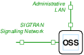
5.1.6 Administrative Node J
Interconnection of the Administrative Node J is illustrated in Figure N-6.
Overview
| TDM Interface: | None. |
| Network Interface: | Administrative LAN. |
| SIGTRAN Signalling Network. | |
| Protocol Components: | M2PA, M2UA, M3UA. |
| Load Generation: | None. |
| Inter-Machine Trunks: | None. |
| Op. Measurements: | None (collection only). |
| Test Harness: | TETWare Distributed Master. |
Description
As listed in Table T-1, logical node J isa n Administrative node interconnected to other nodes in the system via the Administrative LAN.
The node does not require an SS7 narrow-band signalling link interface.
The node is connected to the Administrative LAN as well as the SIGTRAN Signalling Network. The purpose of the SIGTRAN Signalling Network is to provide for experiments that wish to spoof into that network. The node will provide the M2PA, M2UA and M3UA SIGTRAN protocols for use by attack scripts.
Physical Node Mapping
The preferred physical node mapping for logical node J is to provide a separate physical node for the logical node. As a minimal system, logical node J could be combined with the MGC/ASP node I on the same physical node.
5.2 Physical Nodes
Logical nodes can be mapped into physical nodes in two ways:
- Preferred Mapping.
Preferred mapping is to provide a separate physical node for each logical node.
- Minimalist Mapping.
Minimalist mapping combines multiple logical nodes onto each physical node.
5.2.1 Preferred Physical Node Mapping
The preferred mapping of logical nodes onto physical nodes is to provide a separate physical node to host each logical node.
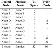
The preferred mapping allows the use of 2U server chassis that can support a maximum of 2 PCI expansion cards. The mapping requires 8 server chassis and 10 T400P-SS7 cards.
5.2.2 Minimal Physical Node Mapping
The minimal mapping of logical nodes onto physical nodes combines like-nodes with complementary interface requirements onto the same physical node.
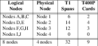
The minimalist mapping requires 2U or 4U server chassis that must support a maximum of 4 PCI expansion cards. The mapping requires only 4 server chassis and 9 T400P-SS7 cards.
6 Hardware Specification
6.1 Hardware Requirements
6.1.1 Compute Hardware
As an efficiency, commodity compute hardware can be used in the SS7/SIGTRAN/VoIP Security Network.
Carrier-grade compute platforms provide redundant processors in hot-swap serviceable, fault-tolerant architectures with the highest level of availability achievable in the industry. However, carrier-grade compute platforms normally correct for transmission facility outages that are the effect of physical or atmospheric changes. Whether a system protects against these items are of no moment in the investigation of signalling system security, and, thus, commodity compute platforms can be used, lowering the overall system cost significantly.
Carrier-grade compute platforms17 are normally equipped to operate on 48 VDC power instead of commercial 110 VAC or 220 VAC power. With the sole exception of the Central Office environment, providing a 48 VDC power source can be far more expensive than normal 110/220 VAC power. Thus, the use of commodity compute platforms further lowers the overall system cost.
Because of the need for specialized interface cards to provide interface to the SS7 signalling network using narrow-band and high-speed SS7 links, the compute hardware cannot be reduced to a commodity blade processor. 2U or 4U rack-mount systems are required to house the necessary interface cards and provide sufficient access for the associated cabling.

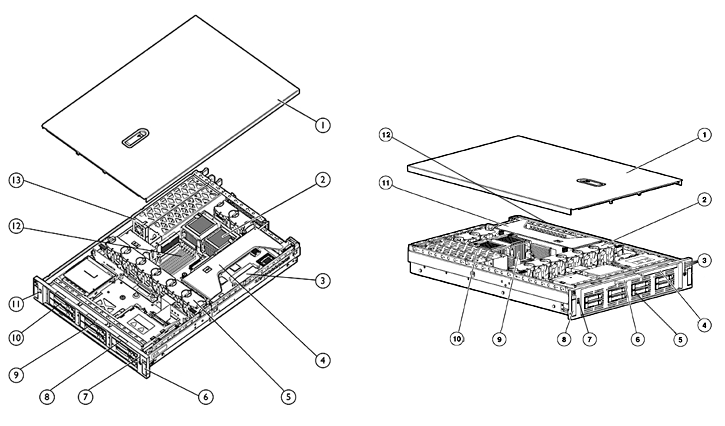
A disadvantage of using commodity compute platforms powered by 110 VAC and using high-performance Intel or AMD processors is rack space, noise, cooling, power consumption and preventative maintenance. Large scale platforms built with commodity 1U or 2U servers require a far greater amount of rack space, a heavier cooling load; because they are forced air cooled, a generate a far greater amount of noise (than the carrier-grade convection cooled systems), consume much more power (primarily due to processors and the necessary cooling fans), and require a higher degree of preventative maintenance (forced air cooling requires filter packs to be changed, and otherwise results in packing the equipment with dust).
There are three suitable 2U rack mount servers for the SS7/SIGTRAN/VoIP Security Network physical nodes:
6.1.1.1 Dell PowerEdge 2850 2U Rack-mount Server
The Dell PowerEdge 2850 2U Rack-mount Server18 is a rack mount optimized E7820 chip set based solution from Dell. The server is illustrated in Figure 9c.
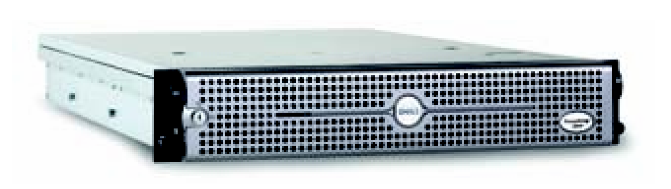
Operating System Support
- Red Hat Linux Enterprise v2.1
- Red Hat Linux Enterprise v3
- Red Hat Linux Enterprise v3 AS EM64T
Features
- 2U rack mount
- Intel Xeon Processor up to 3.80 GHz/800 MHz FSB and Dual-Core Intel Xeon Processor 2.80 GHz
- 1 or 2 processors
- 2MB L2 cache per processor core
- 12GB 400MHz DDR2, 6 DIMM slots
- 3 PCI-X slots (64bit/133MHz) or two PCI-E (1x4 and 1x8 lane) and one PCI-X slot (64-bit/100MHz)
- 6 hot-swap drive bays
- 1.8TB maximum Ultra320 SCSI storage
- integrated dual Gigabit Ethernet (Intel PRO/1000 MT or MF)
- 1 or 2 700W power supplies
- hot swappable power supply, fans and hard disk drives
- optional RAID dual channel ROMB (PERC 4e/Di), PERC 4/DC and PERC 4e/Dc adapters
- optional PowerVault 110T internal tape driver (consumes 1 drive bay)
- IPMI, optional slot-free DRAC 4/I management
- E7820 Chip Set
Target System Cost
Advantages
- 3 full profile PCI-X slots accepting Universal PCI cards.
- Integrated slot-less RAID.
- Lowest cost.
Disadvantages
Applications
The Dell servers are the lowest cost for high end systems making it a good solution choice. The IBM systems are only slightly more expensive; however, and provide additional memory and PCI-X expansion capabilities over the Dell solution. One factor that could decide between the two are the types of systems that UNT is used to.
The Dell servers are, nevertheless, a very usable solution for all but the minimal logical node to physical node mapping (see Table T-3): the servers simply cannot house the necessary interface cards for the full minimal solution. If physical node 2 (as shown in Table T-3) were to be split into two physical nodes, then the expansion capabilities of the Dell servers would be just sufficient; however, it would also take splitting physical node 3 in the minimal system (as shown in Table T-3) to ensure that one PCI-X expansion slot remains available in each physical node. Therefore, a reasonable minimal system would require 6 servers at $3,892.00, or $23,352.
Full blown system cost with the Dell servers would run about $44,496, making the Dell solution more attractive for the full blown system. The full blown system will be cost estimated using the Dell server solution.
6.1.1.2 IBM xSeries x346 2U Rack-mount Server
The IBM xSeries x346 2U Rack-mount Server21 is a rack mount optimized E7820 chip set based solution from IBM. The server is illustrated in Figure 9b.
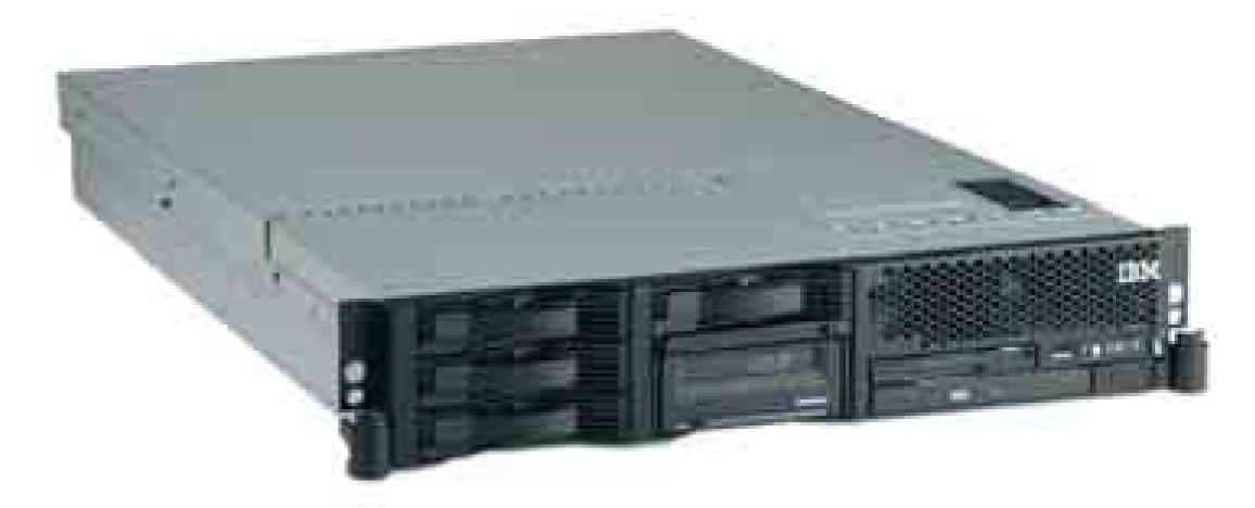
Operating System Support
- Red Hat Linux
- SuSE Linux
Features
- 2U rack mount
- Intel Xeon Processor up to 3.80 GHz/800 MHz FSB and Dual-Core Intel Xeon Processor 2.80 GHz
- 1 or 2 processors
- 2MB L2 cache per processor core
- 16GB PC2-3200 DDR2, 8 DIMM slots
- 4 PCI-X22 or 2 PCI-X and 2 PCI-Express
- 6 hot-swap drive bays
- 1.8TB maximum Ultra320 SCSI storage
- integrated dual Gigabit Ethernet (Broadcom NetXtreme 5721)
- 1 or 2 625W power supplies
- hot swappable power supply, fans and hard disk drives
- integrated RAID-0/1, and optional RAID-5 (on daughter card)
- optional 36/72GB DDS5 internal tape drive (occupies 2 drive bays)
- IPMI, optional slimline remote supervisor adaptor II management
- E7820 Chip Set
Target System Cost
Advantages
- Provides 4 PCI-X expansion slots accepting Universal PCI expansion cards, although two are full profile and two are low-profile, this provides one additional PCI-X expansion slot over the other featured servers.
- RAID 5 slot-less upgrade.
- More flexible memory arrangement. (8 DIMM slots versus 6 on other systems.)
- Comparable cost on low-end system.
Disadvantages
- More costly that equivalent Dell solution on high-end system.
- Will not accept 3 full profile Universal PCI expansion cards.
Applications
The IBM system costs about the same as the Dell solution for low-end systems but provides better expansion for system upgrade. Unfortunately, the 4 PCI-X expansion slots are not all full length; therefore, not even the IBM servers will provide the minimal logical to physical node mapping. Nevertheless, the 4 PCI-X slots will make reconfiguring the system for VoIP experiments easier because the addition of one or two additional GigE LAN cards is possible.
The IBM systems are a very usable solution, an, even though they cannot provide for the full minimal logical node to physical node mapping (see Table T-3), when configured for 6 server nodes the cost is $24,750 but each server will have 2 low-provide PCI-X expansion slots and 4 DIMM slots available per server versus the Dell solution which would only have 1 full profile PCI-X expansion slot and 2 DIMM slots available per server.
Full blown system cost with the IBM servers would run about $49,904, making the Dell solution more attractive for the full blown system. The minimal system will be cost estimated using the IBM solution.
6.1.1.3 HP Proliant DL380 G4 2U Rack-mount Server
The HP (formerly Compaq) Proliant DL380 G4 2U Rack-mount Server25
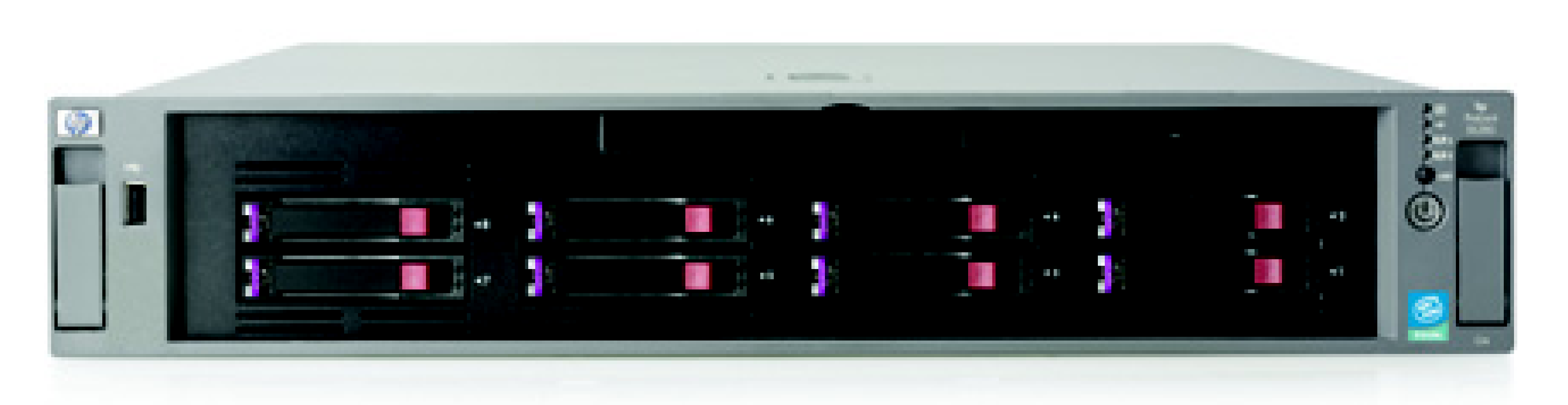
Operating System Support
- Red Hat Linux
- Novell (SuSE Linux)
Features
- 2U rack mount
- Intel Xeon Processor up to 3.80 GHz/800 MHz FSB and Dual-Core Intel Xeon Processor 2.80 GHz
- 1 or 2 processors
- 2MB L2 cache per processor core
- 12GB 2-processor interleaved 400MHz DDR2 SDRAM, 6 DIMM slots
- 3 full length PCI-X expansion slots (optional PCI-E)
- 6 hot-swap driver bays
- 1.8TB Ultra320 SCSI (optional SAS) storage
- integrated dual Gigabit Ethernet (NC7782)
- 575W hot-plug power supply
- optional redundant fan
- integrated Smart Array 6i RAID-0/1 and RAID 5 controller
- optional DAT (40 or 72) tape driver (consumes 1 drive bay)
- IPMI, HP integrated lights-out management
- E7820 Chip Set
Target System Cost
Advantages
- 3 full profile PCI-X slots accepting Universal PCI cards.
- Integrated slot-less RAID 5.
Disadvantages
- Highest cost.
Applications
The HP server solutions are comparable in features to the Dell systems (they have the same 3 PCI-X expansion slots and only 6 DIMM slots), however, they carry a significantly higher cost. Minimal system costs would be $26,598 and full blown system cost would be $53,768. The IBM solution is more attractive for the low-end minimal system of 6 nodes, and the Dell solution is more attractive for the high-end full blown system of 8 nodes.
The HP solution will not be included in either the minimal or full blown system costing.
6.1.2 TDM Interface Cards
The T400P-SS7 and E400P-SS7 cards are 4-span T1 or E1 cards manufactured by Varion. These cards were previously manufactured by Digium. Figure 10 shows a picture of a T400P-SS7 card.
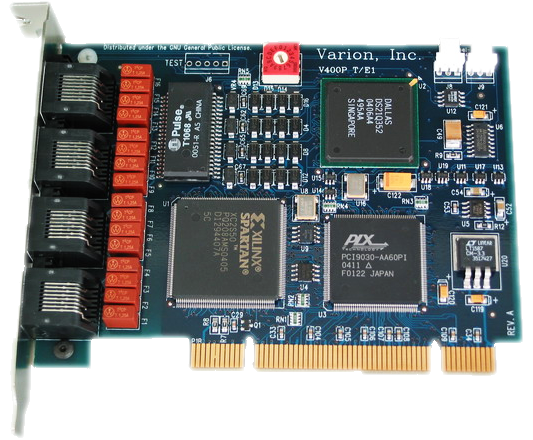
The T400P-SS7 and E400P-SS7 cards have the lowest level of signalling performance due to the lack of on-board HDLC functions. Transfers to the host processor over the PCI bus use PCI I/O ports and memory mapping.
Driver
These cards are supported by the X400-SS7 driver.
The function of the T/E400P-SS7 Channel driver is to provide for the termination of 2.048Mbps, 1.544Mbps, 64kbps and 56kbps digital paths. This driver provides direct access to the channelized or unchannelized T1 or E1 digital paths to OpenSS7 media and signalling protocol modules as well as providing T1 or E1 management, framing, coding, alarms, and synchronization.
Features
Following are the features of the T400P-SS7 and E400P-SS7 cards:
- 4 T1 or E1 spans per card.
- Dallas framer.
- PLX PCI 9030 PCI bus chip.
- Xilinx Spartan XC2S50 processor.
- Raw transfer of octets from framers to PCI bus.
- Uses OpenSS7 Soft-HDLC engine for SS7, ISDN and ISO.
- 96 channels per card (T400P-SS7)
- 124 channels per card (E400P-SS7).
- Full span addressable.
Target System Cost
- $699.00 Each
- $625.00 5-9
- $599.00 10+
Advantages
Following are the advantages of the T400P-SS7 and E400P-SS7 cards:
- Low cost.
- PC Compatibility.
- Released by Jim Dixon under the GNU Public License.
- Open Hardware design: schematics, artwork and Gerber plots available.
- Flash programmable Xilinx chip.
- Field upgradable.
- Supports a number of Open Source drivers.
- Asterisk driver support.
Disadvantages
Following are the disadvantages of the T400P-SS7 and E400P-SS7 cards:
- Lower performance.
- No on-board HLDC.
- Cannot TDM switch on card or between cards, media channels must be transferred through host to switch between cards.
- I/O Port and Memory Map instead of PCI DMA bus-mastering and burst transfers.
- Does not run on high speed buses.
- No integrated Ethernet for SIGTRAN and VoIP applications.
- Synchronization per-card instead of per-system.
Ultimately, the performance limiting factor of the T400P-SS7 and E400P-SS7 cards is the bandwidth of the PCI bus and the ability of the processor to perform Soft-HDLC and TDM switching in software.28 These cards are very cost-effective and can provide 64kbps SS7 links at average incremental interface cost of less than $7.00 USD per signalling link.
Application
For the High-Performance SS7/SIGTRAN/VoIP Security Network nodes, the performance is more than adequate. A high grade 3.20 GHz 4-way 2U server should be capable of handling as many cards as can be equipped in the chassis (2-4 cards totalling 248-496 narrow-band signalling links) with adequate excess processor capacity available for background operations such as load generation and operational measurements collection.
To allow for maximum system reconfiguration, each physical node will be equipped with 2 T400P-SS7 cards, each on an independent PCI bus. The T400P-SS7 are universal 32-bit PCI bus cards and will therefore operate on most PCI segments provided by popular server boards. Each card provides interface for 4 T1 spans
For TDM card cabling, see Digital Cross-Connect.
The full blown system requires 10 cards at $599.00 for $5,990.00. The minimal system only requires 9 cards at $625.00 is $5,625. Because of the discount point at 10 cards, the relative costs of the two systems is comparable as far as interface cards is concerned.
It is typical to run E1 systems in the laboratory when the pricing of E1 is the same as T1. An additional 7 channels per span or 28 channels per card are available on the 2.048 Mbps E1 spans over those available on the 1.544 Mbps T1 spans. However, if the system is even intended on interconnecting with other North American systems, T1 cards should be used.
6.1.3 Network Interface Cards
A number of the physical nodes in the system require high-speed Ethernet network access to one (1) or two (2) signalling or control networks, and lower-speed Ethernet access to one (1) administrative network. For maximum flexibility, server boards should be equipped with on-board dual 1000/100/10baseT autos-ensing Gigabit Ethernet, and either on-board 100baseT Ethernet or the addition of a 1000/100/10baseT PCI interface card for administrative LAN termination.
Note that in the logical node configuration (see Logical Nodes), only Node I requires more than two LAN connections, and then only when VoIP security is to be investigated. The server solutions (see Compute Hardware) all provide slot-less dual GigE, therefore, the physical node supporting logical Node I, will be equipped with two additional GigE cards as required. Note that Node I does not require TDM interface cards (T400P-SS7) and has all three (or four in the case of IBM) PCI-X expansion slots available.
6.1.4 Direct Access Storage Devices
Direct Access Storage Devices (DASD) can be quite expensive. Most of the logical nodes in the SS7/SIGTRAN/VoIP Security Network do not have a requirement for large capacity storage devices. Speed is of more of an issue than size: 2 x 15,000 rpm 38GB SCSI devices in a RAID 1 arrangement or 3 x 15,000 rpm 38GB SCSI devices in a RAID 5 arrangement (striped and mirrored) is preferred. RAID 1 will be provided on the low-end minimal IBM systems and RAID 5 provided on the high-end Dell systems in the full blown configuration.
6.2 Site Requirements
6.2.1 Equipment Enclosures
Equipment enclosure will be one (1) 19-inch rack mount enclosed equipment bay with elevation view as illustrated in Figure E-1 and with the plan view as illustrated in Figure E-2.

The equipment enclosure requires approximately 8 square feet of clearance (2 feet deep by 4 feet wide) at the read of the enclosure and approximately 12 square feet of clearance (3 feet deep by 4 feet wide) at the front of the enclosure.
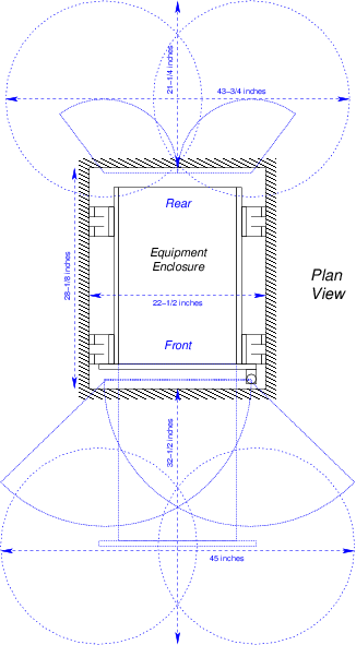
6.2.2 Synchronization
TDM network synchronization will derive from logical nodes D and E (LEC STPs) in a hierarchal synchronization arrangement. Logical node D will provide master synchronization and logical node E will slave from logical node D. All other nodes will slave their synchronization on a per-span basis from their attachment to either logical node D or E.
6.2.3 Time Source
Logical nodes D and E will also act as a time source for Network Time Protocol. If UNT can provide NTP network access to a high accuracy stratum clock, logical nodes D and E will slave off of that NTP source via the Administrative LAN. All other logical nodes in the system will synchronize their local clocks to NTP broadcasts from logical nodes D and E on the Administrative LAN.
6.2.4 Digital Cross-Connect
To allow for system reconfiguration and monitoring access, the SS7/SIGTRAN/VoIP Security Network platform will provide digital cross-connect capabilities. To avoid costly Digital Automatic Cross-Connect System (DACCS) equipment, digital cross-connect (DSX) will be performed on a per-span (T1) basis (DSX-1).
One 56 position 19" rack-mount Bantam jack cross-connect panel (wire-wrap or RJ-48c rear) and cabling will be required. Each T400P-SS7 T1 interface card has 4 RJ-48c jacks. Each physical node contains 2 T1 cards for a total of 8 T1 spans per node. Seven (7) physical nodes with eight (8) spans each will require a 56 position DSX-1. Cabling will be performed using clad category 5 UTP with an RJ-48c connector at one end, and wire-wrap connection at the rear of the DSX for all 56 positions. If minor growth of the system is anticipated, a 64 position DSX-1 should be provided instead.
Twenty-eight (28) 18-inch long dual Bantam patch cables will be required initially to interconnect the nodes in the system.
6.2.5 Network Switching
Network switching is required for 5 networks as follows:
- Administrative LAN.
- SIGTRAN Network.
- VoIP Control Network.
- VoIP Signalling Network.
- VoIP Bearer Network.
Either five (5) 8-port Gigabit Ethernet switches can be provided, or, for the purpose of reducing the amount of equipment required, the SIGTRAN and VoIP Control networks can be combined on a single switch, and the VoIP Signalling and VoIP Bearer networks can be combined on a single switch, for a total of three (3) 8-port Gigabit Ethernet switches. For signalling system security experimentation, only 3 of the 5 switches are required (the VoiP Signalling and VoIP Bearer LANs are not implemented). For signalling system security experimentation, only 2 of the 3 switches are required.
These Ethernet switches should be rear mountable 19" rack mount 8-port (or higher) auto-sensing 1000/100/10baseT Gigabit Ethernet switches with 16-32 Gigabit capacity, RJ45, Category 5e UTP compatible.
6.2.6 Noise
Although equipment enclosures can be equipped with doors that reduce noise from cooling fans inside the equipment enclosure, cooling fans produce a considerable amount of noise. Equipment enclosures should not be located in an office environment that is frequently occupied by personnel. Equipment enclosures should be located in dedicated equipment rooms.
6.2.7 Cooling Requirements
Estimations of steady state operational cooling requirements (BTU-hours of A/C) are based on average operating AC power consumption (i.e. heat dissipation).
6.2.8 Preventative Maintenance
Cooling fan filter packs must be inspected on a regular basis and changed as required. Filter pack lifetimes will depend upon the air quality of the environment in which the equipment is operated.
6.2.9 Power Consumption
Power consumption is estimated by adding the power consumption of the each of the components in the equipment chassis. All components are provided with 110/220VAC 60Hz power. Servers consume 5 to 7 amps each at 110VAC. Network switches consume 1 amp at 110VAC. Total power consumption of the minimal system under full operation is approximately 32amps@110VAC or approximately 3 kilowatts; the full blown system, 60amps@110VAC or approximately 6 kilowatts.
6.3 System Software
OpenSS7 software requires a GNU/Linux operating system to be installed and operational on all physical nodes.
6.3.1 Operating System Software
OpenSS7 protocol software will operation on almost any 2.4, 2.6 or 3.x kernel Linux distribution. The selected GNU/Linux distribution should meet the following criteria:
If the compute platforms are provided by UNT or a third party hardware vendor, the GNU/Linux distribution selected should be one that is supported for the selected hardware. Suggested distributions are vendor-supported enterprise versions such as SuSE Enterprise Linux, or RedHat Advanced Server. Recent unsupported community distributions such as Debian, Fedora Core, or OpenSuSE can also be considered.
OpenSS7 runs strict SELinux security policies on all platforms with remote logging and security scans enabled.
The price of supported version of Red Hat Enterprise Server or SuSE 9 Enterprise Server are not included in the price of the servers (see Compute Hardware). Suitable RHEL clones such as Lineox or WhiteBox are sufficient and will save up to $9,000 on the minimal system and $12,000 on the full blown system.
6.3.2 Network Element Software
OpenSS7 network element software consists of the latest non-public release of the OpenSS7-0.9.2 software package (currently at patch level D). Software is installed and upgraded using RPM on RPM-compatible systems (e.g. SuSE and RedHat) and DSCs on Debian systems.
Network element software will be custom configured for the SS7/SIGTRAN/VoIP Security Network detailed in this design document.
6.3.3 Test Harness Software
Test harness software consists of a current load of the networked version of the TETWare package available in version 3.3h from the OpenGroup web server.
Components for use in TETWare attack scripts (test cases) and components for collection of operational measurements, events, alarms and studies for report generation, will be provided as part of the OpenSS7-0.9.2 package.
6.3.4 Software Commissioning
Commissioning of node software will be priced separately.
6.4 Capacity and Sizing
Capacity of the SS7/SIGTRAN/VoIP network was sized to provide 4 million BHCA derived from a theoretical 10 million residential subscriber base and the minimal system should be capable of sustaining these traffic loads continuously. The complete system should be capable of up to ten (10) times that signalling traffic load, or 40 million BHCA on an effective subscriber base of 100 million residential subscribers.
However, available SS7 signalling links in the system will limit the load to 6 million BHCA at .40 Erlang per signalling link. At 1 Erlang per signalling link, 12 million BHCA on a subscriber base of 30 million residential subscribers could be possible.
The system will be loaded to the maximum capacity possible.
6.5 Hardware Manifest
The sub-sections that follow provide a summary manifest of the hardware components discussed in this document for both the complete system and the minimal system. Also provided is a cost estimate for each system.
6.5.1 Minimal System Manifest and Cost Estimate
Estimated costs are from manufacturer retail prices and does not include any hardware commissioning costs, applicable taxes, nor shipping. Software and software commissioning costs are not included.
6 | IBM xSeries x346 Servers | $4,125.00 | $24,750.00 |
1 | 32U rack mount enclosure | $1,000.00 | $*1,000.00 |
2 | 8-port GigE Switch | $**250.00 | $***500.00 |
1 | 56 position DSX-1 | $**899.00 | $***899.00 |
9 | T400P-SS7 Cards | $**625.00 | $*5,625.00 |
1 | System console | $1,500.00 | $*1,500.00 |
- | PDU and cabling | $**800.00 | $***800.00 |
| =========================== | | ========== |
| TOTAL | | $35,074.00 |
6.5.2 Complete System Manifest and Cost Estimate
Estimated costs are from manufacturer retail prices and does not include any hardware commissioning costs, applicable taxes, nor shipping. Software and software commissioning costs are not included.
8 | Dell PowerEdge 2850 Servers | $5,562.00 | $44,496.00 |
1 | 48U rack mount enclosure | $1,500.00 | $*1,500.00 |
3 | 8-port GigE Switch | $**250.00 | $***750.00 |
1 | 56 position DSX-1 | $**899.00 | $***899.00 |
10 | T400P-SS7 Cards | $**599.00 | $*5,990.00 |
1 | System console | $1,500.00 | $*1,500.00 |
- | PDU and cabling | $1,000.00 | $*1,000.00 |
| =========================== | | ========== |
| TOTAL | | $56,135.00 |
Index
| Jump to: | A C D E G H I L M N O P R S T X |
|---|
| Jump to: | A C D E G H I L M N O P R S T X |
|---|
Short Table of Contents
Table of Contents
- Executive Overview
- Preface
- 1 Introduction
- 2 System Requirements
- 3 Network Configuration
- 4 Instrumentation
- 5 Node Configuration
- 6 Hardware Specification
- Index
Footnotes
(1)
It should be noted that UNT has not written even a high-level requirements document for the instrumentation required for experimentation. The requirements in the sections that follow derive from discussions with Dr. Ram Dantu of UNT and consideration of the paper SS7 over IP: Signaling Interworking Vulnerabilities.
(2)
Note that the use of real MGs, IMTs (Inter-Machine Trunks) and RTP channels for high traffic volumes is cost prohibitive. Costs approaching that of the PSTN itself would result. Call emulation consisting of the signalling components without the actual bearer-channel facilities can provide large-scale signalling traffic approaching that of a large network provider without the cost of the physical trunks. Also, the security of the MEGACO/H.248 or MGCP protocols is not the subject of current investigations and will not be implemented.
(3)
That is, to determine, for example, how many call failures were caused by a particular experiment, and the nature and extent of each failure.
(4)
Current investigation focusses on the signalling component and not the bearer component.
(5)
An example of PSTN line-side device and interfaces are ISDN basic rate or ISDN primary rate interfaces, and BRI ISDN sets and PRI NT1s are an example of PSTN line-side devices.
(6)
An operational measurement study invokes the collection of operational measurements not normally collected on a regular basis.
(7)
ITU-T Recommendation Q.752, "Specification of Signalling System No. 7 – Monitoring and Measurements for Signalling System No. 7," Jun 1997, (Geneva), ITU, ITU-T Telecommunication Standardization Sector of ITU. (Previously "CCITT Recommendation")
(8)
Ibid.
(9)
Ibid.
(10)
Ibid.
(11)
Ibid.
(12)
Virtualization does not completely partition the platform into multiple virtual platforms: for example, hardware that can be reset directly, such as Ethernet cards, will become unusable for all virtual machines and thus all logical nodes.
(13)
The lower CCS and holding times within the range are typical of residential (non-dial access) lines; the higher values in the range, indicative of business lines.
(14)
Whether node ‘I’, the MGC/ASP node, provides an MTP layer, or a portion of an MTP layer, is dependent on the SIGTRAN protocol used: if M3UA or SUA is used in the non-SG as STP arrangement, the MGC/ASP does not provide any portion of an MTP layer; if M2PA or M2UA is used, at least some portion of the MTP is provided by the node.
(15)
1,000,000 BHCA equates to about 4630 T1s of bearer circuits which would require approximately $1,000,000.00 worth of equipment to fully realize.
(16)
1,000,000 BHCA equates to about 4630 T1s of bearer circuits and over 100,000 RTP sessions which would require over $1,000,000.00 worth of equipment.
(17)
Even the commodity based NEBS-3 compliant 4U servers HP c3310 and IBM x343 are normally equipped with -48 VDC power.
(18)
Dell does not seem to provide a NEBS-3 compilant solution.
(19)
The low end system is two 3.2GHz Xeon, 2GB SDRAM, RAID 1 2 x 15k RPM 38GB SCSI, redundant power.
(20)
The high end system is two 2.8GHz Dual-Core Xeon, 4GB SDRAM, RAID 5 3 x 15k 38GB SCSI, redundant power.
(21)
IBM also provides a NEB-3 compatible telco-grade server, the x343, however, this server is quite expensive by comparison to the x346 (about three (3) times the cost) and is only provdided in a -48VDC power option.
(22)
Note that 2 PCI-X slots are normal profile and the other 2 PCI-X slots are low-profile slots.
(23)
The low end system is two 3.2GHz Xeon, 2GB SDRAM, RAID 1 2 x 15k RPM 38GB SCSI, redundant power.
(24)
The high end system is two 2.8GHz Dual-Core Xeon, 4GB SDRAM, RAID 5 3 x 15k 38GB SCSI, redundant power.
(25)
HP also provides the NEBS-3 compatible telgo-grade server, the c3310, however, this server is only available in 1-way Xeon configurations, consumes 4U of rack space, is available with AC power, but not support dual integrated Gigabit Ethernet and is quite costly by comparison to the DL380 G4.
(26)
The low end system is two 3.2GHz Xeon, 2GB SDRAM, RAID 1 2 x 15k RPM 38GB SCSI, redundant power.
(27)
The high end system is two 2.8GHz Dual-Core Xeon, 4GB SDRAM, RAID 5 3 x 15k 38GB SCSI, redundant power.
(28)
A 350MHz processor is capable of processing the bandwidth of an entire E400P-SS7 card (124 signalling links) with a combined link throughput of 8.192 Mbps.
Copyright © 2014 OpenSS7 Corporation All Rights Reserved.